EXPERIMENTS AT IMFT:

The experimental work planned at IMFT is focusing on three types of flames:
- WP1: Small laminar flames controlled by H2 injection.
- WP2: Turbulent swirled two-phase flames controlled by H2 injection.
- WP3: Flames stabilized on porous burners
WP1: Small laminar flames controlled by H2 injection.
Premixed laminar flames are found in stoves, domestic heaters, industrial process heating burners. They are interesting prototypes for SCIROCCO because making these burners compatible with PtG strategies (iebeing able to burn H2 in these systems) would be a great improvement in many regions of the world. The problem addressed in SCIROCCO can be formulated as follows:
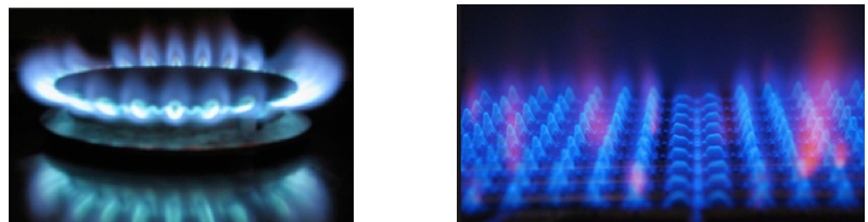
Examples of burners targeted in WP1: a stove (left) and a domestic heater (right). The laboratory flames studied at IMFT will mimic the features of these devices.
‘Having a burner designed to burn methane or propane, similar to those above, can we modify it to inject hydrogen “somewhere” to make this system more efficient: less prone to instabilities, able to operate in ultralean conditions with extended LBO limit, with controlled noise and pollutant emissions (NOX, CO, soot) ? Can we also ensure ‘fuel flexibility’ which means being able to go from 0% of H2 to 100 % of H2with minimal changes in the burner geometry ?’.
The answer to the last question is critical for PtG strategies where H2 would be produced locally (in a farm for example) and burnt locally too, either in conjunction with another gas or pure if no fossil fuel is available.
These studies also require to consider the effects of H2 injection on pollutants such as NOx which may be adversely affected by H2addition and must be kept under control. NOx levels will be measured in the IMFT experimental rigs and computed in the digital twins using complex chemistry descriptions available in AVBP, the code of CERFACS used in SCIROCCO. They will be incorporated in the cost functions used to make decisions on the configurations choice. Experiments will be installed at IMFT and all simulations (which will be Direct Numerical Simulations (DNS) for these small low Reynolds number flames) will be run by IMFT and CERFACS. A typical configuration (a flame stabilized behind a cylinder) for WP1 is displayed in Fig. 5 with 4 possible locations for H2 injection.
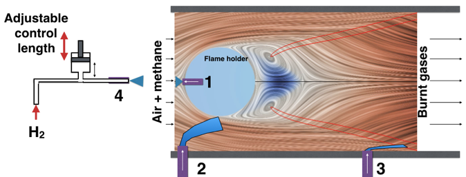
Streamlines and flame position (red line) for a methane / air laminar flame configuration of IMFT with 4 possible hypothetical locations for H2 injection. The flame is stabilized behind the blue cylinder (the ‘flame holder’). Positions 1 to 4 indicate places where H2 injectors could be located. For position 4, an example of ’intrinsically stable’ design using an adjustable impedance system for the H2 line is displayed.
The first location (marked 1) corresponds to the stagnation point upstream of the cylinder, the second one (marked 2) would propel H2 in the boundary layer of the cylinder and then into its wake where the flame is stabilized. The third position (marked 3) would change the flame behavior when it reaches the wall of the chamber: this maybe an interesting zone for injection because flame / wall interaction in these flames is a source of instabilities and pollution. The last location (marked 4) corresponds to a case where H2 would be injected upstream of the flame holder and would have a finite, tunable time to mix with methane before reaching the flame. All these zones are ‘sensitive’ regions where pure H2 injection will have a drastic effect on the flame. The figure also displays an example of simple passive control system to adjust the impedance of the hydrogen line which would be useful to control combustion instabilities. Of course, other locations of injection and other possibilities (such as using multiple simultaneous injection) will also be considered if needed. These various systems of H2 injection will be used to study two classes of problems: the control of combustion instabilities and the extension of the operability domain.
WP2: Turbulent swirled two-phase flames controlled by H2 injection.
The second class of flames studied in SCIROCCO is more complex (Juste 2006, Poinsot 2017) and corresponds to technologies used in furnaces or in gas turbines for propulsion and power generation. In these systems, fuel is injected as a liquid and the flow is ‘swirled’: a strong rotation is added on the mean flow to create more compact, two-phase, turbulent flamesof much higher power than in WP1.
As an example, the figure below shows a swirled injector (similar to the future SCIROCCO injector) and indicates where hydrogen could be introduced. In these complex-geometry injectors, it is not easy to modify the design in order to introduce H2. Fortunately, most of them already include multiple lines to inject fuel because this has been required to develop low NOX, lean burn systems in a long series of European and industrial programs since the 90s. We will focus on systems using low NOx, ‘multipoint’ injections where fuel is injected both at the center of the swirler (near the central plug of the swirler) and at its outer periphery using additional small holes. Therefore, for SCIROCCO, the first two places tested to add hydrogen injection devices will be:
- the ‘plug’ region, which corresponds to the zone located on the swirler axis and
- the ‘multipoint’ holes (or some of these holes) located around the swirler.
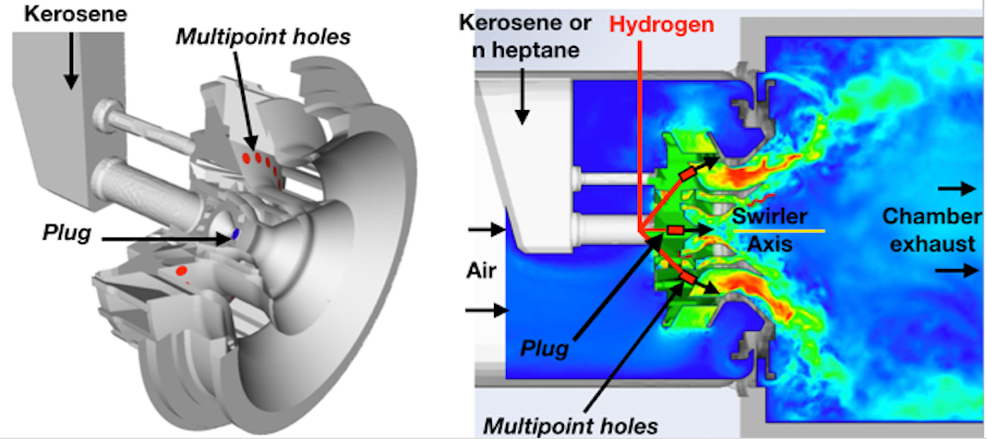
An example of possible H2 injection locations on a modern swirled injector (Jaegle et al 2011). Left: geometry of multipoint injector. Right: instantaneous velocity field (AVBP result). The two possible locations for hydrogen injection are the central plug (on the swirler axis) and the multipoint holes.
These zones can be easily modified to allow hydrogen injection in many modern swirlers so that it will be possible to extend SCIROCCO results to real injectors.
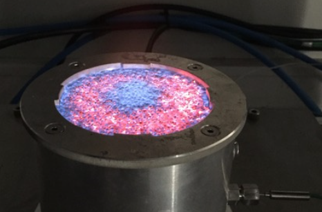
WP3: Flames stabilized on porous burners.
An elegant solution to burn fossil fuels and H2 is to use a porous burner where a flame is stabilized on or in a porous medium.
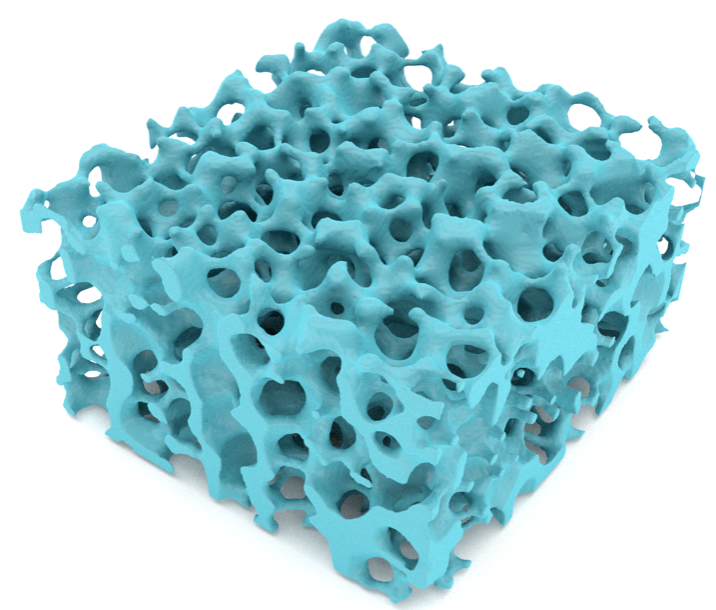
These configurations raise all kinds of fundamental problems which will be addressed in SCIROCCO using experiments, simulations but also purely analytical theoretical approaches. As an example a first test of flames stabilized on a porous burner is displayed below.
REFERENCES
- T. Boushaki,Y. Dhué, L. Selle, B. Ferret and T. Poinsot (2012) Effects of hydrogen and steam addition on laminar burning velocity of methane-air premixed flame : Experimental and numerical analysis. Int. J. Hydrogen Energy37, 9412-9422.
- P. Chiesa, G. Lozza, L. Mazzochi (2005) Using hydrogen as gas turbine fuel. J. Eng. Gas Turbines Power, 127, 73-80.
- O. Colin, F. Ducros, D. Veynante and T. Poinsot (2000) A thickened flame model for large eddy simulations of turbulent premixed combustion. Phys. Fluids 12, 7, 1843-1863.
- R. Donini, RJM Bastiaans, JA van Oijen, LPH de Goey (2017) A 5-d implementation of fgm for the large eddy simulation of a stratified swirled flame with heat loss in a gas turbine combustor. Flow, Turb. Comb.98 (3), 887-922.
- F. Duchaine, F. Boudy, D. Durox and T. Poinsot (2011). Sensitivity analysis of transfer functions of laminar flames, Comb. Flame 158, 2384-2394.
- E&E consultant, HESPUL and SOLAGRO 2014. Study for ADEME, GRTGAZ and GRDF. « Etude portant sur l’hydrogène et la méthanation comme procédé de valorisation de l’électricité excédentaire. »
- T. Emmert, S. Bomberg and W. Polifke (2015) Intrinsic thermoacoustic instability of premixed flames. Comb. Flame162, 1, 75-85.
- A. Felden, L. Esclapez, E. Riber, B. Cuenot and H. Wang (2018). Including real fuel chemistry in LES of turbulent spray combustion. Comb. Flame193, 397–416.
- L.Y.M. Gicquel, G. Staffelbach and T. Poinsot (2012), “Large Eddy Simulation of Gaseous Flames in Gas Turbine Combustion Chambers”, Prog. En. Comb. Sci.38, 782-817. Invited review paper.
- A. A. Hairuddin, T. Yusaf, A. P. Wandel (2014) A review of hydrogen and natural gas addition in diesel HCCI engines. Renewable and Sustainable Energy Reviews, 32, 739-761.
- F. Halter, C. Chauveau, I. Gökalp (2007). Characterization of the effects of hydrogen addition in premixed methane/air flames, Int. J. Hyd. Energy, 32, 13, 2585-2592.
- M. Hoeijmakers, V. Kornilov, I. Lopez Arteaga, P. de Goey and H. Nijmeijer (2014). Intrinsic instability of flame-acoustic coupling. Comb. Flame161, 2860-2867.
- J.P. Hodges, W. Geary, S. Graham, P Hooker &R. Goff (2015). 'Injecting hydrogen into the gas network – a literature search'. Health and Safety Laboratory (HSL) report. RR1047.
- F. Jaegle, J.-M. Senoner, M. Garcia, F. Bismes, R. Lecourt, B. Cuenot and T. Poinsot (2011) Lagrangian and eulerian simulations of evaporating fuel spray in an aeronautical multipoint injector, Proc. Comb. Inst.33, 2099-2107.
- T. Jaravel, E. Riber, B. Cuenot and P. Pepiot (2018). Prediction of flame structure and pollutant formation of Sandia flame D using Large Eddy Simulation with direct integration of chemical kinetics.Comb. Flame 188, 180-198.
- M. Jentsch, T. Trost, and M. Sterner (2014). Optimal Use of Power-to-Gas Energy Storage Systems in an 85% Renewable Energy Scenario. Energy Procedia, 46, 254-261
- S. Jerzembeck, N. Peters, P. Pepiot-Desjardins and H. Pitsch (2009) Laminar burning velocities at high pressure for primary reference fuels and gasoline: Experimental and numerical investigation. Comb. Flame156, 2, 292-301.
- G. Juste, G. (2006). Hydrogen injection as additional fuel in gas turbine combustor. Evaluation of effects. Int. J. Hydrogen En., 31(14), 2112–2121.
- K.S. Kedia, A.F. Ghoniem (2014). The anchoring mechanism of a bluff-body stabilized laminar premixed flame, Comb. Flame, 161, Issue 9, 2327-2339.
- H. Kobayashi (2018). Science and technology of ammonia combustion. Plenary lecture at the 37th Symp. (Int.) Comb. Dublin, Ireland, 28 July- 3 August.
- A. Konnov (2008) Remaining uncertainties in the kinetic mechanism of hydrogen combustion, Comb. Flame152, 4, 507-528.
- A. Konnov, A. Mohammad, V. Ratna Kishore, N. Il Kim, C. Prathap, S. Kumar (2018) A comprehensive review of measurements and data analysis of laminar burning velocities for various fuel+air mixtures, Prog. En. Comb. Sci.68, 197-267.
- C. Kraus, L. Selle and T. Poinsot (2018). Coupling heat transfer and large eddy simulation for combustion instability prediction in a swirl burner. Comb. Flame 191, 239-251.
- J. Lamouroux, M. Ihme,B. Fiorina and O. Gicquel (2014). Tabulated chemistry approach for diluted combustion regimes with internal recirculation and heat losses. Comb. Flame, 191(8) 2120-2136
- J. Li and A.S. Morgans. (2016). Feedback control of combustion instabilities from within limit cycle oscillations using H∞ loop-shaping and the ν-gap metric. Proc. R. Soc. A472 (2191), 20150821.
- F. Lückoff, M. Sieber, C.O. Paschereit and K. Oberleithner (2018) Characterization of Different Actuator Designs for the Control of the Precessing Vortex Core in a Swirl-Stabilized Combustor. J. Eng. Gas Turb. Power140 (4), 041503.
- K. McManus, T. Poinsot T. & S. Candel (1992) “A review of active control methods for combustion instabilities”, Progress in Energy and Combustion Science19, 1-29.
- M. Miguel Brebion, D. Mejia, P. Xavier, F. Duchaine, B. Bedat, L. Selle and T. Poinsot (2016). Joint experimental and numerical study of the influence of flame holder temperature on the stabilization of a laminar flame on a cylinder. Comb. Flame. 172, 153-161.
- K. Nithyanandan, Y. Lin, R. Donahue, X. Meng, J. Zhang, C. F. Lee (2016). Characterization of soot from diesel-CNG dual-fuel combustion in a CI engine, Fuel184, pp:145–152.
- P. Pepiot and H. Pitsch (2008). An efficient error-propagation-based reduction method for large chemical kinetic mechanisms. Comb. Flame154, 67–81.
- H. Pitsch (2006). Large Eddy Simulation of Turbulent Combustion. Ann. Rev. Fluid Mech. 38, 453-482.
- T. Poinsot (2017). Prediction and control of combustion instabilities in real engines. Hottel plenary lecture. Proc. Comb. Inst.36, 1-28.
- T. Poinsot and D. Veynante (2011) “Theoretical and numerical combustion”. Used worldwide for combustion courses. elearning.cerfacs.fr/combustion/onlinePoinsotBook/buythirdedition.
- K. Prieur, D. Durox, T. Schuller and S. Candel (2017) A hysteresis phenomenon leading to spinning or standing azimuthal instabilities in an annular combustor. Comb. Flame. 175, 283-291.
- T. Schaaf, J. Grünig, M. Schuster, T. Rothenfluh, and A. Orth (2014). Methanation of CO2 - storage of renewable energy in a gas distribution system. Energ. Sustain. Soc.4 (1) p. 2.
- G.P. Smith, D.M. Golden, M. Frenklach, N. Moriarty, B. Eiteneer, B., M. Goldenberg, C.T. Bowman, R. Hanson, S. Song, Jr Gardiner et al., 1999. GRI 3.0 Mechanism. Gas Research Institute http://www.me.berkeley.edu/gri mech.
- A. Urbano and L. Selle (2017). Driving and damping mechanisms for transverse combustion instabilities in liquid rocket engines. J. Fluid Mech., 820, R2–12.
- H. Wang, R. Xu, K. Wang, C.T. Bowman, R.K. Hanson, D.F. Davidson, K. Brezinsky and F.N. Egolfopoulos (2018). A physics-based approach to modeling real-fuel combustion chemistry - I. Evidence from experiments, and thermodynamic, chemical kinetic and statistical considerations, Comb. Flame, 2018, in press, ISSN 0010-2180, doi.org/10.1016/j.combustflame.2018.03.019.
- P. Xavier, A. Ghani, D. Mejia, M. Miguel-Brebion, M. Bauerheim, L. Selle and T. Poinsot (2017) Experimental and numerical investigation of flames stabilised behind rotating cylinders: interaction of flames with a moving wall, J. Fluid Mech., 813, pp. 127–151.
- P. Xavier, L. Selle, G. Oztarlik and T. Poinsot (2018). Phosphor Thermometry on a rotating flame-holder for combustion applications. Exp. Fluids 59, 2.
- Yang and S. Pope (1998) Treating chemistry in combustion with detailed mechanisms - In situ adaptive tabulation in principal directions - Premixed combustion. Comb. Flame112, 85-112.
- L. Zhang, S.-C. Kong (2010). Vaporization modeling of petroleum–biofuel drops using a hybrid multi- component approach, Comb. Flame, 157, 2165–2174.
Published on September 12th, 2019